OVERMOLD TOOL DESIGN – LEVERAGING EXPERIENCE TO OPTIMIZE THE PERFORMANCE OF YOUR MEDICAL DEVICE ASSEMBLY
Designing and fabricating mold tooling for the overmolded assemblies process is one of the key and core competencies at ClearPath Medical. It’s one of the foundational pieces that ensures proper mechanical function and aesthetics can be delivered reliably and repeatedly. Selection and understanding of how certain substrates and cable jacket densities will perform is a key characteristic when designing mold tooling, one that is benefitted by years of experience producing high quality medical cable assemblies.
Along with design considerations, capabilities of equipment and processes should also be addressed when designing overmold tools. Wall thickness, shot size, and runner/gate design should all be considered to deliver an optimized design. The location and size of gates should be reviewed so OEM’s have full understanding of potential flow and cosmetic attributes. Tool designers should also consider the material flow behaviors to ensure complete filling during the molding process. At the end of the day, tool design for overmolding is not a complete science but design engineers can draw upon their experience and provide solutions to permit the best possible outcome. In all cases, a steel-safe approach is warranted to achieve critical-to-quality features on a molded or overmolded medical device assembly.
WHAT IS A STEEL-SAFE APPROACH
Injection Molds require some amount tweaking after sampling to achieve the final product’s design intent. Some examples of common tweaks are:
- Minimizing potential for flash onto substrates and cable jackets
- Thickening of wall sections
- Controlling tight tolerance features
- Part Textures
When considering mold design a simple thought holds true: More plastic material in the part requires less steel in the mold. Less plastic material in the part requires more steel in the mold.
Removing steel is relatively easy but adding steel to an already made mold requires welding or installing new inserts to modify the tooling for the updated design. Welding molds and/or installing new inserts results in more expense to the OEM.
Equipped with this knowledge, when developing new mold tooling, design engineers will identify steel-safe opportunities by reviewing critical-to-quality (CTQ) or critical-to-function (CTF) geometries early in the design process. Those features require special attention and can be tweaked by removing steel to achieve the final dimensional or cosmetic requirements. This leaves much more maneuverability to modify the tooling to achieve the best possible results with the least amount of expense to the OEM.
OVERMOLD TOOL COMPONENTS
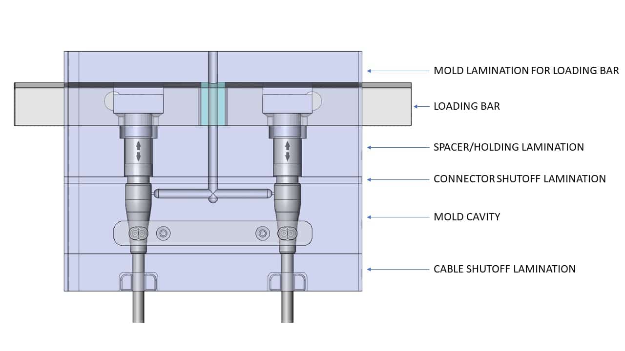
Let’s dive into what makes up a ‘tool’. The components that make up tooling for medical device overmolding are generally common and typically include:
- Cavities: This part of the tool will produce the body of the overmolded component. Some examples here include yokes and strain reliefs.
- Loading Bars: Securely holds the connector housings, pins or other components allowing operators to install assemblies efficiently and accurately into the proper position and orientation of the mold tooling.
- Cable Shutoffs: Holds the cable exiting the strain relief in the proper position during overmolding. It is often desirable to be able to use raw cable with different overall diameters for the same connector size/type. If the shutoff tooling is separate from the strain relief tooling, accommodating different cable diameters can more easily be accomplished.
- Strain Relief: The portion of the tool which molds a solid or segmented bend relief, joining and potentially sealing between the connector and the cable jacket material.
- Miscellaneous: Many molds require inserts or laminations that are not directly associated with the molded product. Some examples are runner transitions, holding plates and spacer plates.
MOLD TOOLING MATERIALS
During the scoping of product specifications, normally the life of the product is defined. Depending on the service life of the product, several options are available for selection of mold tooling materials. Aluminum, pre-hard steel, and hardened steel are the most common for production of medical cable assemblies. Choosing the most appropriate material to fabricate mold tooling depends on production volume and life expectancy of the program. Three of the most popular mold material styles include:
Aluminum (6061 or 7075):
- Prototyping or low-volume production <1,000 shots
- Quicker tool fabrication lead time
- Lower cost due to no heat-treat/secondary finishing process
P20 Pre-Hard Steel
- Prototyping or low-volume production <50,000 shots
- Quicker tool fabrication lead time
- Lower cost due to no heat-treat/secondary finishing process
Hardened Stainless Steel (420 SS):
- Extended Volume Up to ~1,000,000 shots
- Lengthier lead time due to heat-treatment of tool and post finishing operations
- Low risk of diminished parting lines and oxidation
SINGLE OR MULTI-CAVITY MOLDS
Deciding whether to use single or multi-cavity molds is another decision that must be tackled during the planning phases of a project. This decision should be based on the production volume over the lifetime of the product. While typically more costly, multi-cavity molds allow two or more parts to be molded at once, increasing output and reducing the unit cost of each molded part. Designing and fabricating tools with a single cavity is less costly than multi-cavity tools, but lower up-front costs may be offset by higher production unit costs. It’s important to really understand project budget and estimated consumption prior to overmold tool design.
COLLABORATION AND TIMELINE
Customer communication and design input is essential to medical device tool design and on-time completion. Early and regular collaboration between the customer’s project and engineering team and the OEM manufacturing team is important throughout the project but is even more significant until the product design is frozen. Tooling fabrication is typically the longest lead item of a project, ranging from 4 – 14 weeks depending on complexity and selection of mold tooling materials. While tooling is being fabricated, documentation is completed, and other raw materials are ordered. Scheduling weekly design reviews, will help ensure that both the customer and cable manufacturing partner stay on-target and on-time while meeting the established product requirements.
TOOL OWNERSHIP
It is common for OEM customers to pay for and own production tooling. When this is the case, the tooling is only used to produce parts for that tool owner. In some instances, the OEM may elect to share the cost and ownership of the tool in which case, use is not exclusive. In some cases, cable manufacturers may own stock tooling that is available for customer use. Examples of stock tooling that ClearPath Medical carries are ECG Snap, DIN 42802-1 and -2 leads, Connector Strain Reliefs (LEMO/REDEL, ODU) and various lead accommodating yokes.
SUMMARY
We might argue that designing overmold tooling and taking into careful consideration each of its components is one of the most critical steps towards successful medical device design and manufacturing. It truly is a foundational element that will ensure that medical products are designed to meet or even outlast their performance requirements, in addition to the overall look and feel. It’s a process that needs to be taken with diligence and thought, and what that we put at the forefront of our work here. Contact us and learn more about how we can improve the life, function, and look of your finished medical cable assembly.